Dynamic Relaxation

Introduction

Dynamic relaxation is a method commonly used for form finding of shell structures. It was introduced by Alistair Day [1] and solves the nodal position \mathbf{x}_a for each node a in the structure in such a way that nodal equilibrium is fulfilled

\mathbf{p}_a + \sum\limits_b \mathbf{f}_{ab} = \mathbf{0},

in which \mathbf{p}_a is the sum of all the applied external loads and the support reaction if the node is restrained, and \mathbf{f}_{ab} the internal force in member ab ending in node a.

As long as the position is incorrect a out of balance or residual force appears at each node

\mathbf{p}_a + \sum\limits_b \mathbf{f}_{ab} = \mathbf{r}_a.

By introducing a small time step \delta t and a fictitious mass m_a at each node, we can trace the structure’s (fictitious) motion in time as it moves towards the equilibrium position.

To update the position
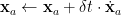
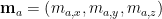
 \mathbf{x}_a for node a, the following three operations are performed consecutively

\ddot{\mathbf{x}}_a \gets \mathbf{r}_a/m_a,
\dot{\mathbf{x}}_a \gets \mu \cdot \dot{\mathbf{x}}_a + \delta t \cdot \ddot{\mathbf{x}}_a,
\mathbf{x}_a \gets \mathbf{x}_a + \delta t \cdot \dot{\mathbf{x}}_a,

where \ddot{\mathbf{x}}_a and \dot{\mathbf{x}}_a are the acceleration and velocity of the node, respectively, and \mu is a damping parameter introduced to ensure numerical stability.

Fictitious mass

The mass is fictitious and adjusted to adjusted to optimise the rate of convergence [2] and usually taken as

m = \frac{\left(\delta t\right)^2}{2}S,

where S is the largest direct stiffness occuring at the node during the simulation. Further strategies on choosing the fictitious mass is discussed in [3], including using different masses in different directions, effectively turning the mass in to a vector \mathbf{m}_a=\left(m_{a,x}, m_{a,y}, m_{a,z}\right).

Axial stiffness

If there only exists axial stiffness in the system, the internal force in member
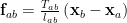
 ab is found from

\mathbf{f}_{ab} = \frac{T_{ab}}{l_{ab}}\left(\mathbf{x}_b-\mathbf{x}_a\right),

where T_{ab} and l_{ab} are the tension in member ab and the current length, respectively. \left(\mathbf{x}_b-\mathbf{x}_a\right)/l_{ab} is a unit vector in the direction from node a to node b.

It should be noted that so far we have discussed pure static equilibrium. No assumptions have been made regarding the material properties of the members which might be linear or non-linear elastic or be subject to creep or plastic deformation. The structure may be statically determinate or indeterminate or even a mechanism, provided that it is in equilibrium. The structure may have undergone a large deformation from some initial state.

In order to determine the form found geometry we need further information regarding the tensions T_{ab} and their relationship with the current lengths l_{ab}. The simplest relationship is linear elastic,

T_{ab} = k_{ab} \left(l_{ab}-l_{0,ab}\right),

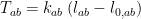
in the case of a member with unstressed length l_{0,ab}. The constant k_{ab} = (EA)_{ab}/l_{0,ab} in which (EA)_{ab} is equal to the Young’s modulus times the cross-sectional area of the member. However, during form finding we can postulate any relationship between tension and length, including inextensible members whose length cannot change and members with a constant tension.

References

[1] A. S. Day. An introduction to dynamic relaxation. The Engineer, 219:218–221, 1965.
[2] M. R. Barnes, “Form finding and analysis of tension structures by dynamic relaxation,” International Journal of Space Structures, vol. 14, no. 2, pp. 89–104, 1999.
[3] M. Rezaiee-pajand, M. Kadkhodayan, J. Alamatian, and L. Zhang. A new method of fictitious viscous damping determination for the dynamic relaxation method. Computers & Structures, 89 (9–10):783–794, 2011.